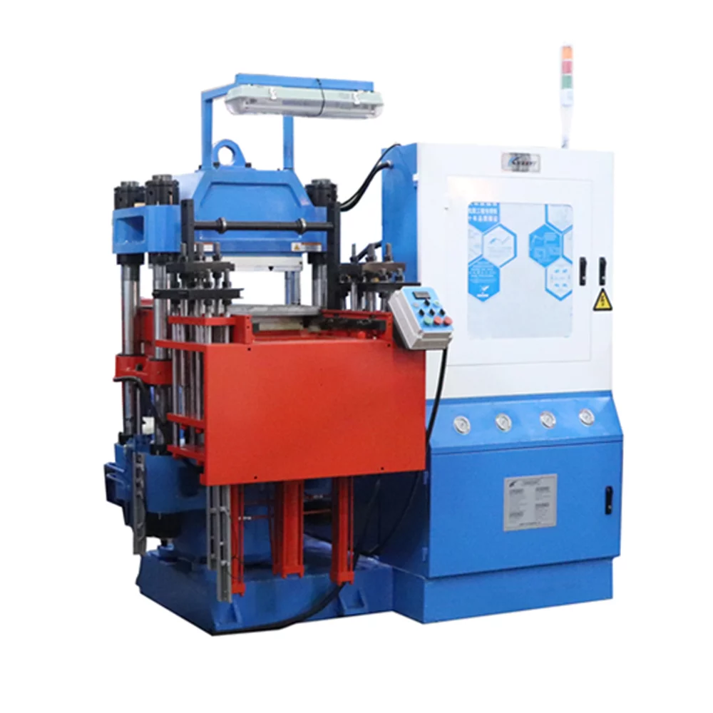
Achieving dimensional consistency in elastomer manufacturing depends heavily on balancing internal cavity pressures with adequate mechanical retention. If the closing pressure is calculated incorrectly, production lines run the risk of structural defects, excessive flash, or accelerated tool wear. Correctly sizing a rubber injection molding machine involves analyzing a combination of part geometry, compound rheology, and hydraulic capabilities.
Industrial facilities often struggle with the choice between over-specifying machine tonnage—which wastes energy and risks crushing tools—or under-specifying it, which causes quality failures. Striking the ideal balance requires a data-driven engineering approach rather than relying on guesswork.
At HWAYI, our engineering department focuses on breaking down these complex calculations into predictable, reliable parameters. By mastering the variables that influence mechanical deflection during the injection stroke, manufacturing plants can maintain stable, long-term production.
Understanding Projected Area and Geometry Fundamentals
The primary foundation for any clamping force assessment begins with the total projected area of the molded component. This measurement represents the flat two-dimensional silhouette of the part as seen from the direction of the clamp closure stroke.
Every square millimeter of this surface area will experience an upward hydraulic force when the raw compound fills the tool. For complex multi-cavity molds, the calculation must include the surface area of all individual cavities plus the integrated runner system.
Failing to account for the full layout of the cold or hot runner channels will lead to a systemic underestimation of the required tonnage. Our development team always recommends mapping out the entire face of the tool layout to establish an accurate base measurement.
The Role of Peak Cavity Pressure and Material Flow
Internal cavity pressure varies drastically throughout the injection, packing, and curing phases of the cycle. Unlike thermoplastics, elastomeric compounds exhibit complex viscous properties that change as the material absorbs thermal energy from the mold platens.
During the filling stage, the viscosity drops, but as cross-linking begins, the resistance to flow increases rapidly. This transformation generates a localized peak pressure within the cavity that tries to force the heavy steel plates apart.
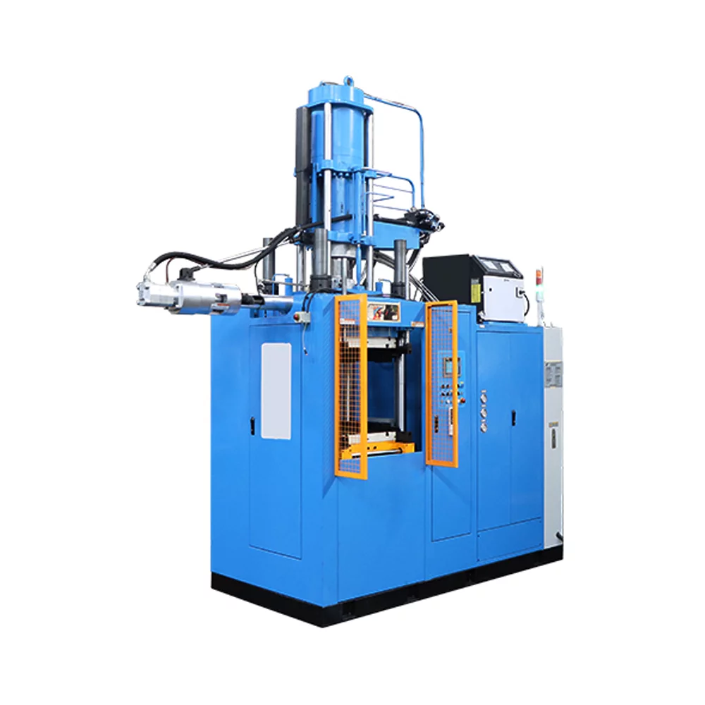
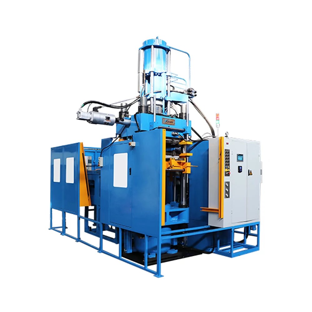
It is vital to choose a robust rubber molding machine with responsive hydraulic feedback. This structural rigidity helps prevent internal material pressure from exceeding the available clamping force.
Analyzing Compound Viscosity and Flow Behavior
Different base polymers possess unique flow characteristics that dictate how much pressure is needed to push them through a tool. High-viscosity materials like EPDM or natural rubber demand significantly more injection force than highly fluid liquid silicone rubbers.
Mooney viscosity ratings offer a starting point for predicting how much resistance a specific batch will encounter inside the runners. A stiffer compound requires a higher holding tonnage because the high internal injection pressures travel directly into the mold split line.
We analyze these distinct rheological footprints closely when configuring specialized machinery options for our global partners. By matching the mechanical clamp profile to the specific elastomeric compound, we protect facilities against premature mold separation issues.
Evaluating Platen Parallelism and Deflection Risks
Even if the calculated tonnage matches the theoretical requirements, physical mechanical misalignments can cause localized clamping failures. Platen parallelism ensures that the calculated force is distributed across every square inch of the mold face.
If a machine frame suffers from minor deflection under load, the clamping pressure drops at the outer edges of the platens. This localized drop allows material to escape, resulting in part flash even though the global tonnage indicator looks correct.
Structural integrity remains a core pillar of our design ethos to prevent these subtle physical discrepancies. Building rigid clamping mechanisms protects sensitive tooling and guarantees uniform pressure delivery across high-density multi-cavity layouts.
Designing for Precision Corner Jointing and Profiling
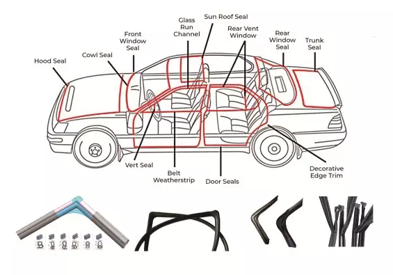
Specialized applications, such as connecting pre-extruded profiles or sealing corners, introduce unique clamping dynamics. These processes require localized high-pressure injection without crushing or deforming the delicate, pre-cured rubber profiles already placed in the tool.
Standard vertical or horizontal presses often lack the specific access and open frame architecture needed to handle long, continuous profiles efficiently. Achieving a clean, seamless joint demands precise mechanical control over a compact, targeted clamping area.
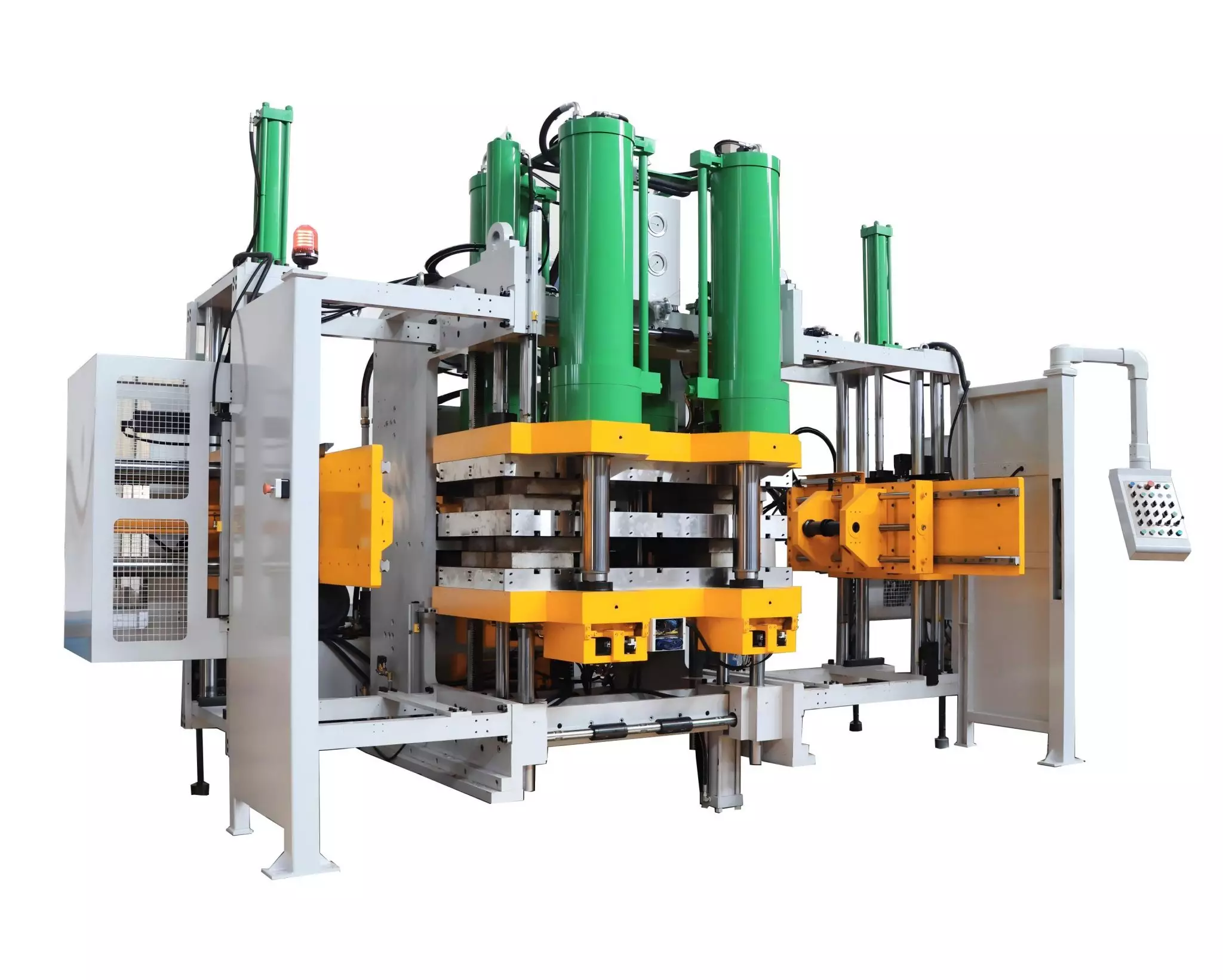
To address these specialized geometries, we developed the EPDM and NBR C Frame Injection Press Machine. This targeted HWAYI rubber machine configuration offers open access for operators while delivering high-precision clamping force exactly where the profile junctions meet.
The Impact of Injection Speed on Clamping Demand
The velocity at which the compound enters the cavity directly alters the maximum pressure seen by the clamping unit. High-speed injection profiles generate massive localized pressure spikes as the material forces its way into the furthest corners of the tool.
While faster filling speeds are desirable to prevent the rubber from scorching, they necessitate a corresponding increase in holding power. Slower injection profiles reduce the peak pressure but extend cycle times and increase the risk of knit-lines.
Processing engineers must carefully balance the injection velocity profile against the available mechanical tonnage of the press. Utilizing multi-stage velocity control allows the system to transition smoothly, keeping internal pressures safely within the clamp limitations.
Incorporating Necessary Engineering Safety Factors
Theoretical calculations provide a solid baseline, but real-world production variables demand the inclusion of a structural safety margin. Fluctuations in ambient temperature, material batch variations, and tool wear can all impact pressure dynamics over time.
Adding a conservative safety factor—typically between fifteen to twenty percent above the theoretical calculation—guards against unexpected process drifting. This buffer prevents intermittent flashing issues and reduces long-term mechanical strain on the hydraulic pumps.
We work closely with plant managers to calculate these operational safety buffers accurately based on historical production data. This collaborative step helps the selected machinery operate well within its safe engineering limits.
Long-Term Benefits of Accurate Tonnage Calibration
Precise clamping force adjustment yields massive operational dividends over the lifespan of a manufacturing system. Optimizing the tonnage minimizes power consumption since the hydraulic power packs only deliver the exact force required.
Furthermore, avoiding excessive clamping pressures extends the operational life of the mold parting lines, core pins, and internal venting channels. Over-clamping seals off vital vents, trapping air inside the cavities and causing visible burn marks on the parts.
By treating clamping force as a dynamic, tunable processing parameter rather than a fixed maximum setting, facilities maximize efficiency. Our technical support teams remain dedicated to helping operations fine-tune these parameters for peak productivity.
Conclusion
Accurately assessing clamping force is a mandatory requirement for achieving consistent product quality manufacturing in industrial rubber processing. By carefully calculating projected surface areas, understanding compound rheology, and choosing rigid machine architectures, facilities protect their tooling investment. Implementing precise tonnage control ensure consistent part quality, reduced energy consumption, and highly repeatable production cycles.